We all know the story. You deploy a network to extremely tight specifications, and when you ask – just to make sure you understand the requirements, of course – if it’s absolutely certain that the client IP ranges will never change, that this system will never need to be accessible from the Internet and that there is no way they will need more than eight host addresses; people just laugh at you and say things like “a fully built-out system can’t physically handle more than five servers, so yeah – we’re never even going to need the eight you’ve given us!”. Of course you know better than to trust project design engineers, so you make sure the system runs on public IP addresses, accessible from anywhere in your network and you set aside 27 (or better make it 59) IPs for host addresses just to be sure; so when they sheepishly come back after three months and say “Umm, we need some help…” you can do the whole Told-You-So-routine and then magically appear to fix the issue within a few minutes. (It’s okay to keep complaining for a couple of hours first.) Again, you’re the hero!
After a couple of years in the industry, you’re bound to run into situations that, while you may have predicted them, you can’t engineer around them easily. I ran into one of those a few years back. We deployed a platform that includes components that were accessible to our end-customer CPEs; and when our customers access certain services, a connection from CPE to server is automatically initiated. The IP address of this system is provided to the CPE from a catalogue server, and due to the architecture of the platform (as given to us by the integrator), there is no way to change this IP once it’s been set – it is hardcoded in too many places. What really tripped me up here was that specific issue, in combination with the two first statements above – from initially being accessible from three private IP ranges, strictly controlled by us, we needed to make sure that this server was suddenly accessible to the Internet. Yay. (Good thing I was clever enough to use a public IP address for the server, huh?)
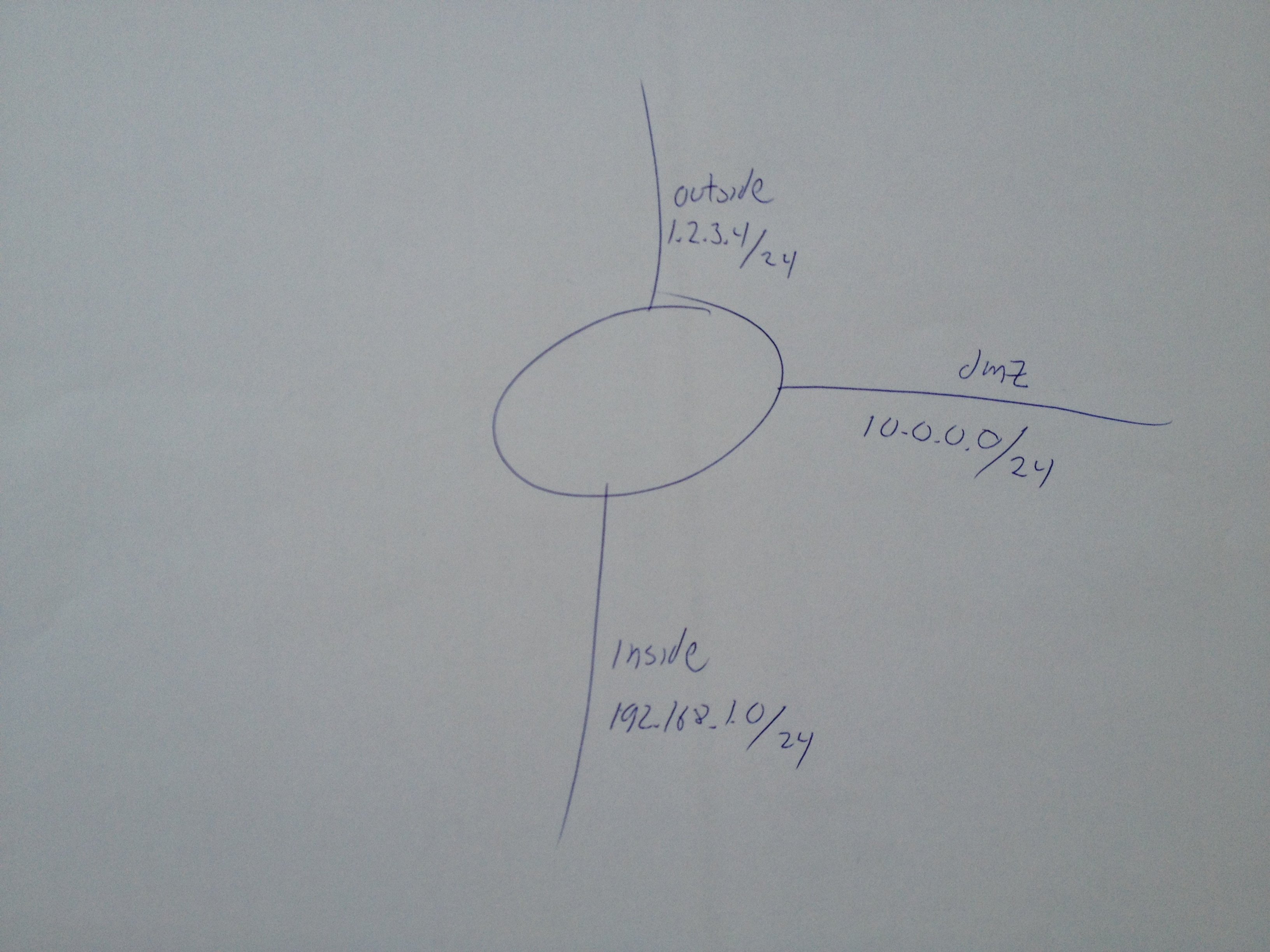
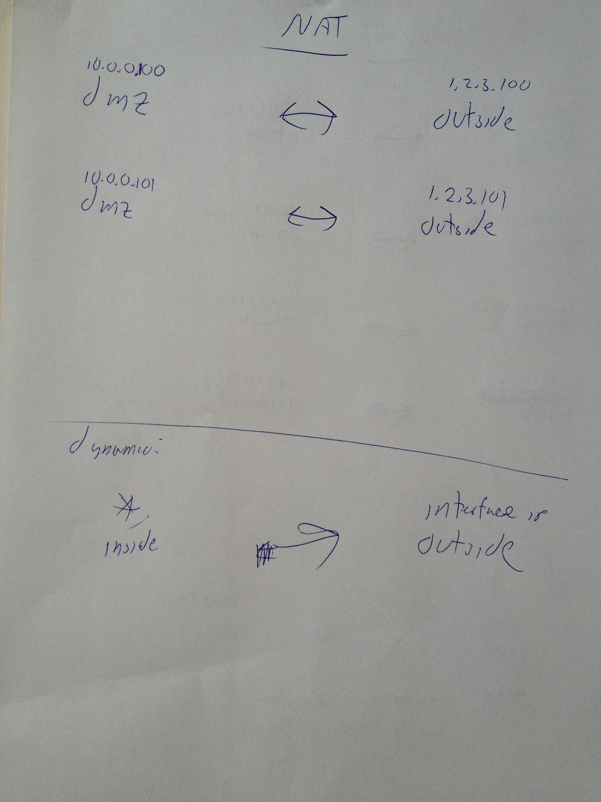
The system, let’s call it DAVE, is connected in a VLAN with a number of other devices that do not need to (in fact, should not) be accessible from the outside world. Before, we knew that all clients allowed through the Cisco ACL was an authorized CPE (there was no way to get an IP address in that range and get so far as to be able to make a request to this server otherwise) but with a wide open ACL, the attack vector is so much bigger, and I want to make sure that DAVE is as secure as possible – there are some strange people on the Internet. After a few false starts with a half-hearted NAT attempt and an attempt at placing DAVE behind a load-balancer and do some clever stuff with layer-7 filters there I gave up (apparently, that version of AlteonOS would only load balance that particular protocol on its IANA assigned port number, not the non-standard port we used) and contacted a consultancy company we work with for assistance, and they came up with a pretty neat solution – using a “Virtual Wire” on a Palo Alto Networks firewall. A true square plug in a square hole solution.
This works exactly like you envision a firewall to work – you have your interfaces, your trust zones, your policies and enough host and group objects to force you to come up with a naming convention for them… There’s only one thing missing that you’d normally expect to find – you don’t actually have any IP addresses on the firewall itself. The firewall acts like a transparent bridge between the two ports – it’s essentially a layer-7 aware patch cable* that you insert between the 6500 and DAVE. (* = Patch cable not included.) DAVE keeps his old IP configuration and the 6500 – and the rest of the VLAN – is none the wiser. In fact, the PA will even bridge DAVE’s MAC address to appear directly on the 6500 access port. (I understand that the Cisco ASA can do something similar – Jimmy will cover this in a later post.)
Configuration is simple – you need to configure the participating interfaces as Virtual Wire interfaces, then create the Virtual Wire itself, and finally configure the zone mappings for the interfaces before you proceed to configure the actual policies as usual. These steps can be performed through the web GUI or via the CLI, and I’ll show you the CLI style here. Policies are better configured through the web GUI, though; but we’ll leave that to a future post if there is interest.
set network interface ethernet 1/1 virtual-wire
set network interface ethernet 1/2 virtual-wire

set network virtual-wire DAVE interface1 ethernet 1/1
set network virtual-wire DAVE interface2 ethernet 1/2
set network virtual-wire tag-allowed 123,456**
set network virtual-wire link-state-pass-through enable yes***

set zone DAVE network virtual-wire 1/1
set zone UNTRUST network virtual-wire 1/2
(**= Allow tagged VLAN’s 123 and 456 through. If you’re on an untagged port, just skip this line.
***= This means that if the link between DAVE and the PA goes down, the PA will bring down the link between PA and 6500; effectively telling the Cisco “DAVE’s not here, man.”.)
That’s the Virtual Wire configured (remember to commit your changes). Now you can have the Palo Alto policies delve into the actual packets and verify the layer-7 contents: Is it properly formed? Does it go to a valid URI? Has it got the correct User-Agent? Does it have a valid session-token? Et cetera. This is another layer of protection the evil-doers will need to get through in order to access DAVE; and it makes me as an admin sleep better at night.